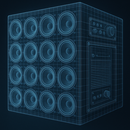
A Digital Horn is an advanced loudspeaker capable of changing the audience areas it covers without any mechanical change — no tilt, no rotation, no movement. A screen of transducers, controlled only by DSP.
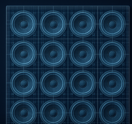
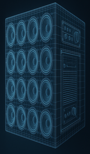
A 16-driver unit — illustrative purposes only. The physical body of the idea.
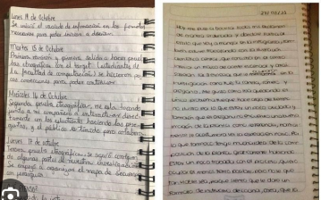
The diaries begin. Every page, a stone on the path.
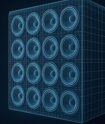
An AI-drawn scheme of a 3D loudspeaker, much like the Digital Horn project envisions it.
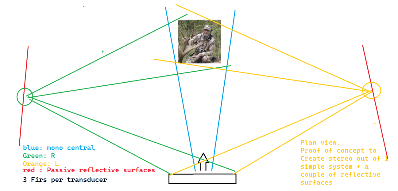
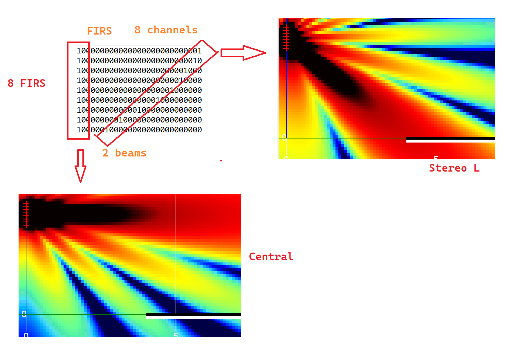
Stereo out of a frontal, mono-looking system.
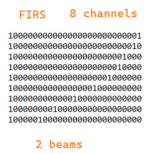
Already done: frequency-dependent stereo from a central cluster. Two FIRs per channel, superposition technique. Something very fancy that appears plausible to do with my current tools — missing only the right loudspeakers.
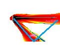
Frequency-dependent stereo from a central cluster.
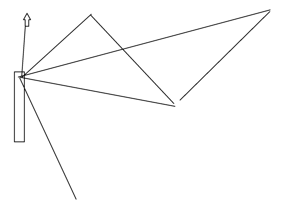
A multi-beam example — two audiences, one body of drivers.
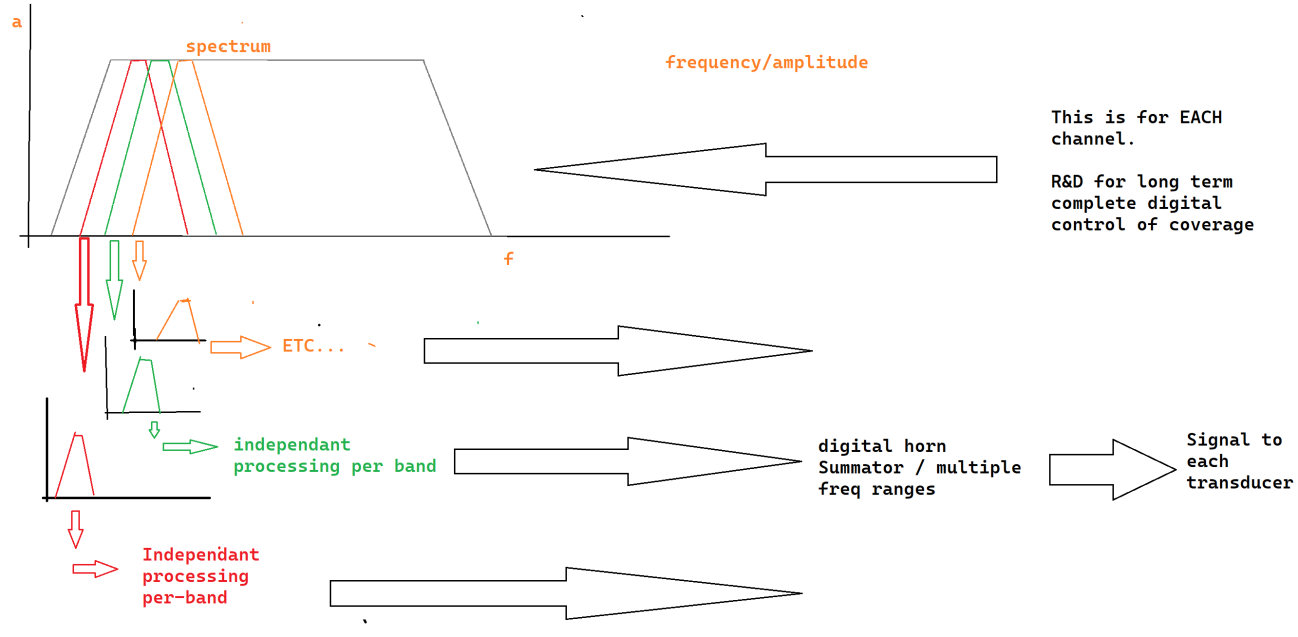
No moving parts. No mechanical change. Only DSP.— the governing principle
Long-term. The horizon we are walking toward.
The importance of dedicated hardware.
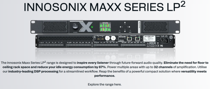
Dedicated hardware for the research is non-negotiable. Linea Research plus a new partnership with a US amplifier manufacturer — these are the legs we stand on.
The dedicated hardware question. Without a close, healthy, active relationship with suppliers, we walk on one leg.
Partnership architecture — where Linea, the amp vendor, and Danley meet.
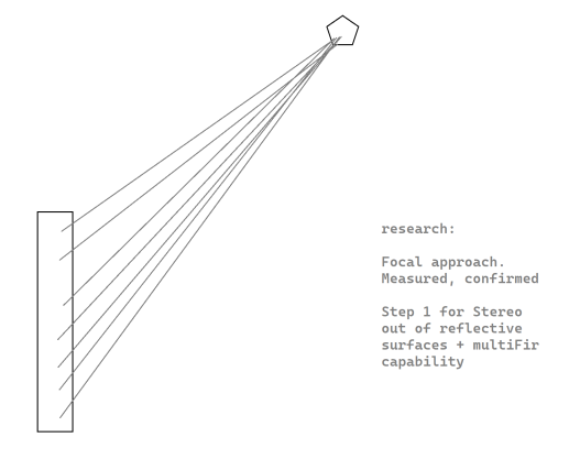
Focal approach — the corner stone.
In the focal approach, we concentrate arrivals to a point or a particular direction. This is the cornerstone for every more advanced algorithm that follows — including the active muting of non-desired lobes.

Step 1 — focal approach. Arrivals concentrated at a single point.
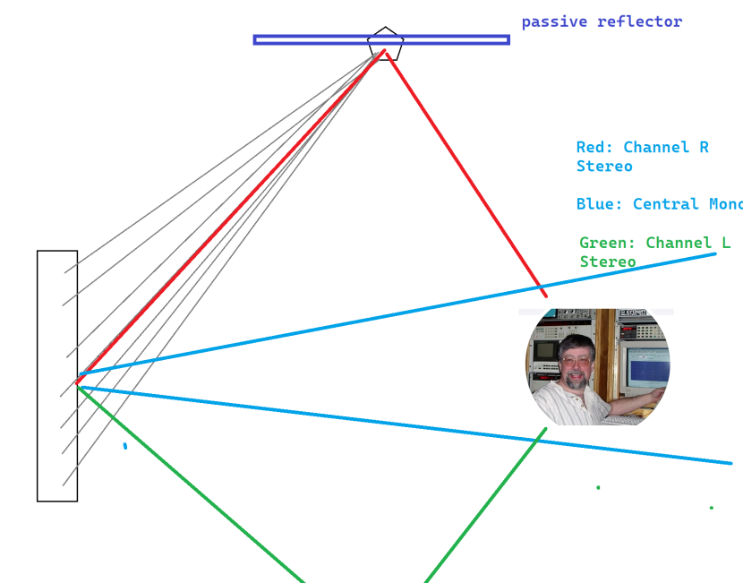
Step 2 — focal plus mono central. Building stereo out of a central cluster.
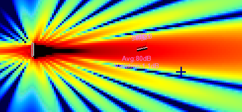
2 kHz, frontal mono. Baseline to compare against.
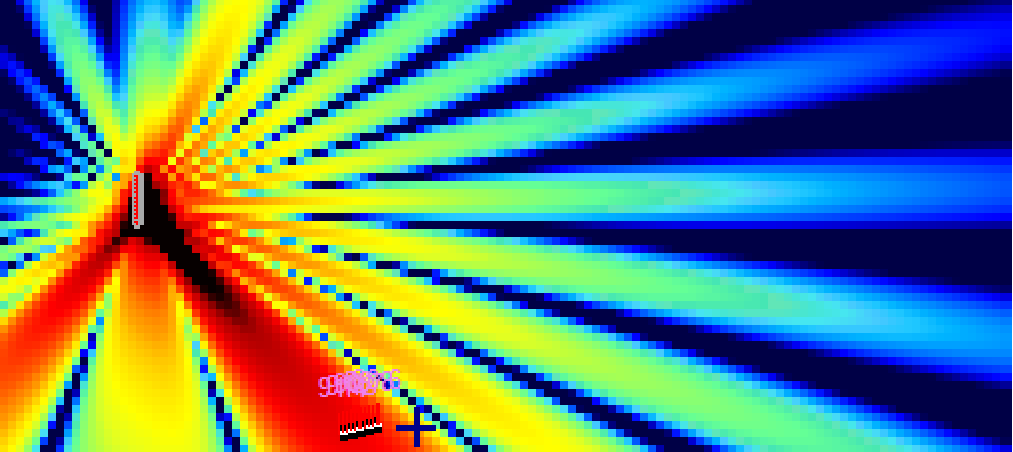
2 kHz, frontal R. Don’t worry about the lobes — we differentiate dark red from green/blue.
Central mono plus channel L. Two FIRs per channel. Superposition technique.
Candidate hardware, first pass.

Candidate hardware, second pass.

Candidate hardware, third pass.
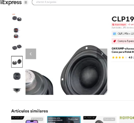
These transducers are not working anymore. We will change them for real ones — Faital, B&C.
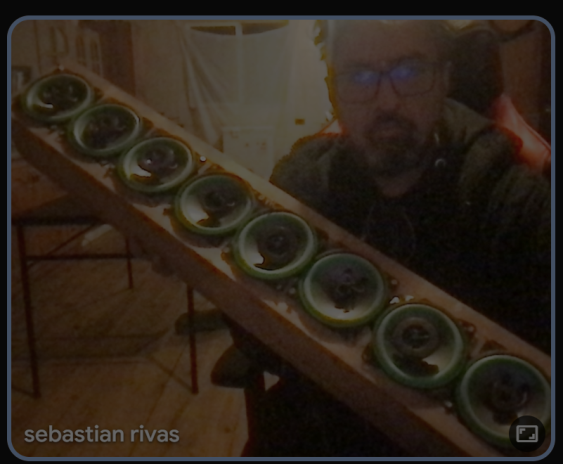
The bench, as it stands.
Prototype geometry, sketched.
The end-terminated product.
In a glance, the end-terminated product should be: N channels, active, each with DSP capabilities. Hopefully 512 to 1024 taps. This will be a very fun way to share how we advance on this project.
The end-terminated product — N channels, DSP per channel, 512–1024 taps, massive FIR loading capability.
Small and big steps to come.
1. Make my 8-channel unit work — a simple line column for research. Capable of stereo out of a central unit plus passive reflectors. Only needs the transducers; the processor for multi-FIR loading is already here.
2. Build a 20-channel unit — the Digital Horn itself. Transducers, processor, amp with FIR capability.
3. Having our own DSP program with an embedded pocket-Direct software to create the beams visually. This pocket Direct is the main matrix where we calculate the FIRs that go to each channel.
4. Final user interface and product finish, aesthetical.
Plus: adding the new impressive DSL summation approaches by Tom. I am sending, this week, the in-Direct tool for creating Digital Horns out of real models — including the one made of SH25s you asked for.
1 month · 5 months · 8 months · 12 months to first real Digital Horn.— rough timeline, arbitrary
Model proposals.
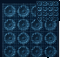
Model DHR01. 20 channels. Speech only. Control from 400 Hz to 2 kHz. 20 × 4" drivers.
Model DHR02. 40 channels. Speech only. Control from 400 Hz to 10 kHz. 20 × 3" + 20 × 1". Scalable up to four units.
DHR02 — two-way, mids and highs arranged so that four units can be summed while keeping the lambda separation constant.
Two units combined. Spacing preserved. +6 dB of power.
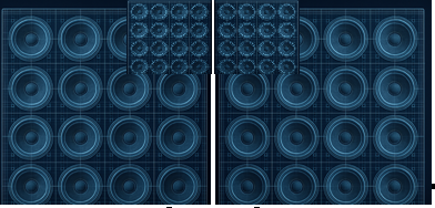
Four units combined. Spacing preserved. +12 dB of power and better control of lows.
These are the Digital Horn diaries, for the Danley Sound Labs team. Already playing and testing stuff. All good, all perfect our new DSP capabilities on FIRs.