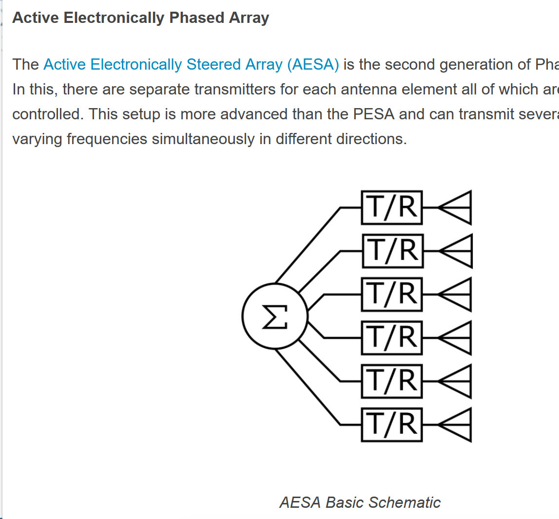
The opening sketch — phased arrays, antennas, and lobes as one family of ideas.
Hi Tom. Yeah, I understand what you are talking about. Now I am super interested on the new summator. Can you send some SketchUp drawing or anything to let me understand better what we are talking about.
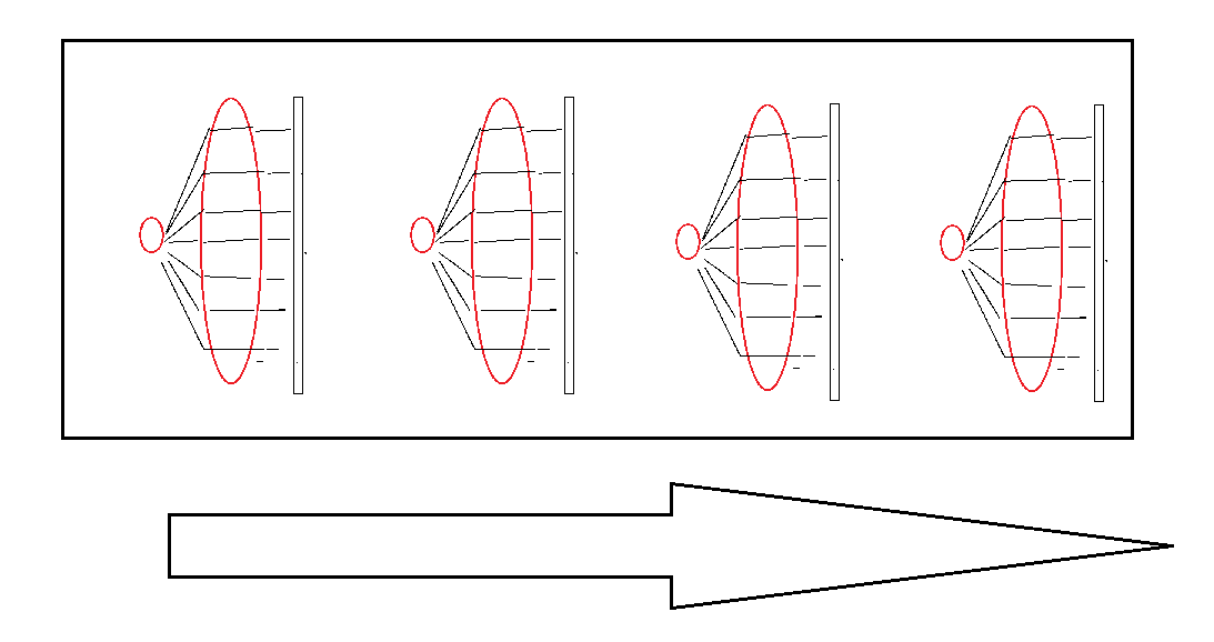
I barely remember the principle behind the paraline. I remember something like —
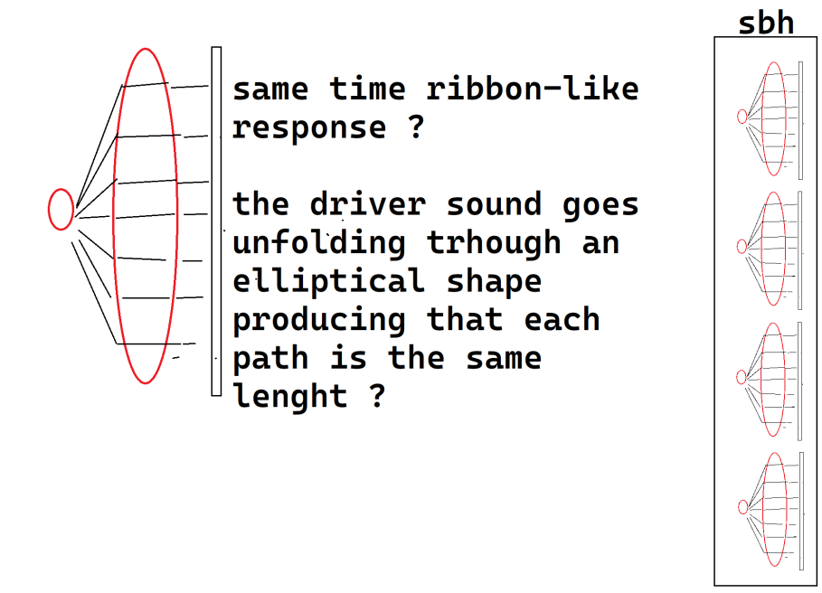
The paraline principle, as I remember it.
And this was already very incredible. I remember the very first days of the SBH series. I always wondered, though, why only the SBH10 and SBH20 were developed and no further. Now if you found a better approach — even better, that would be great.
About the need for a simulation using the SH25 as the starting point, I am all yours. I’ll prepare this as a secret tool inside Direct, like the ones I gave you for investigating the end-fired approaches. About that — what happened with that line of research? Did Mike grasp the concept fully?
End-fired cannon — missing information. A thread to pull on.
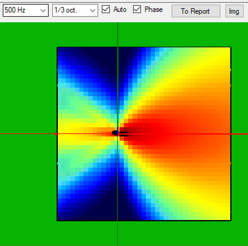
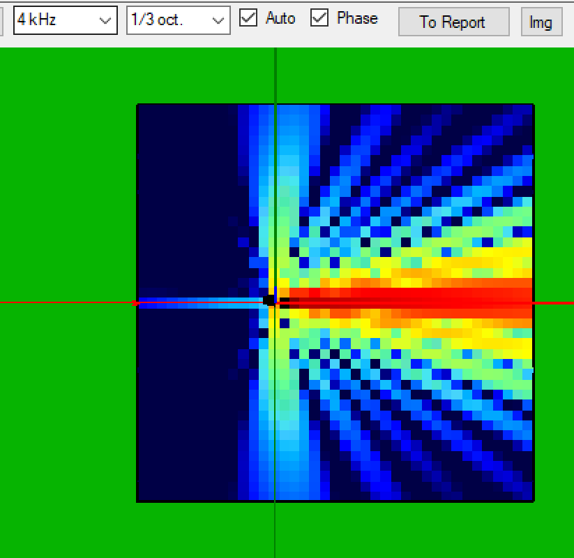
SH25 polar pattern, as a grid.
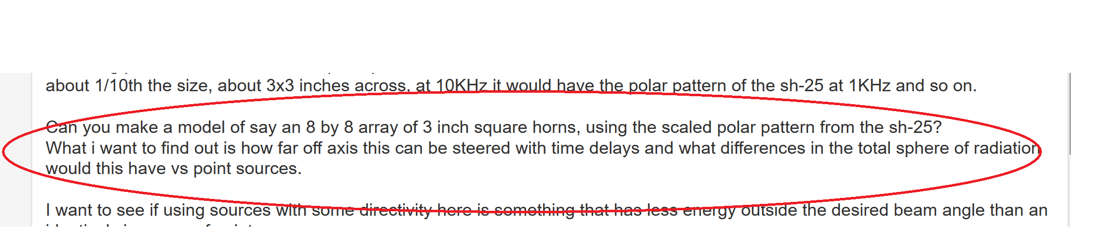
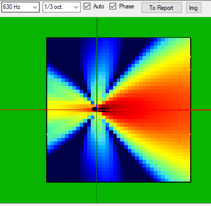
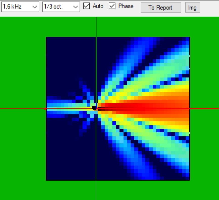
So, with the SH25 polar pattern, a grid of little speakers would behave something like this — from 500 Hz to 5 kHz, frequency by frequency.
SH25-based grid — pattern at a first frequency step.
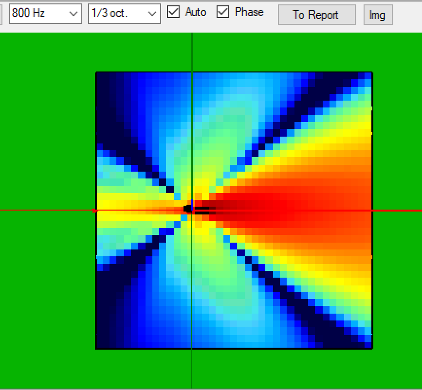
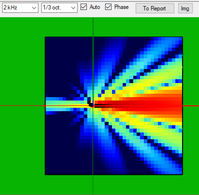
Next frequency step.
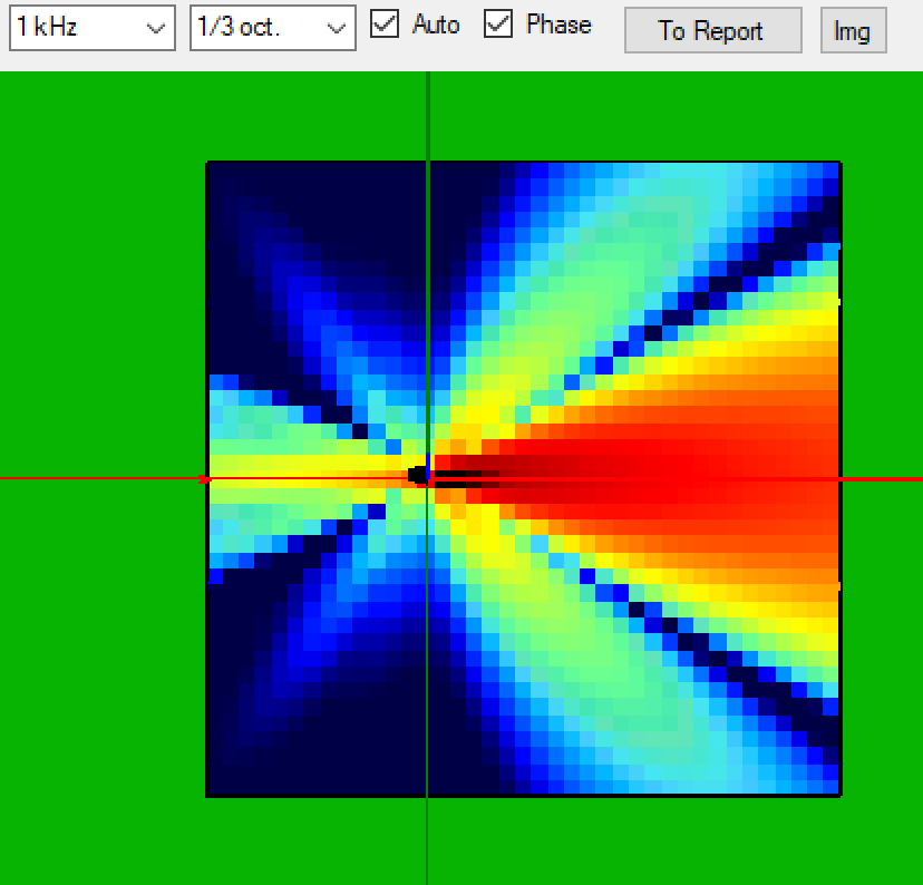
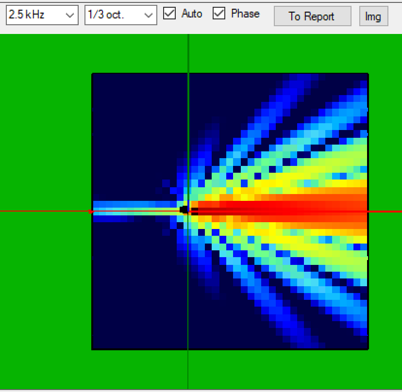
Next frequency step.
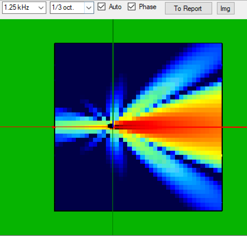
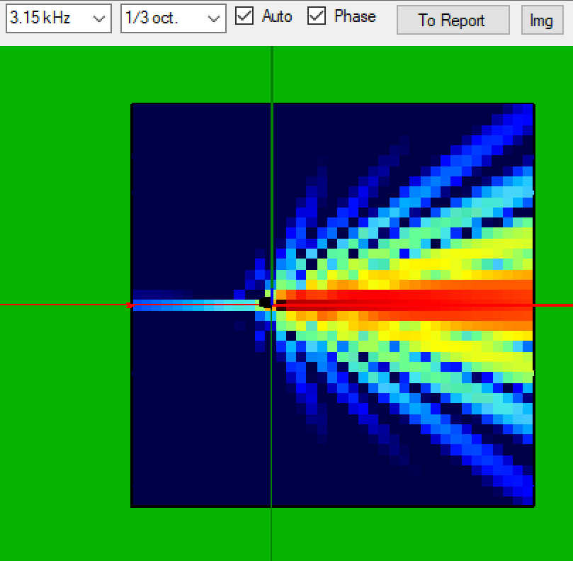
Next frequency step.
Next frequency step.
Next frequency step.
Next frequency step.
Next frequency step.
Next frequency step.
Next frequency step.
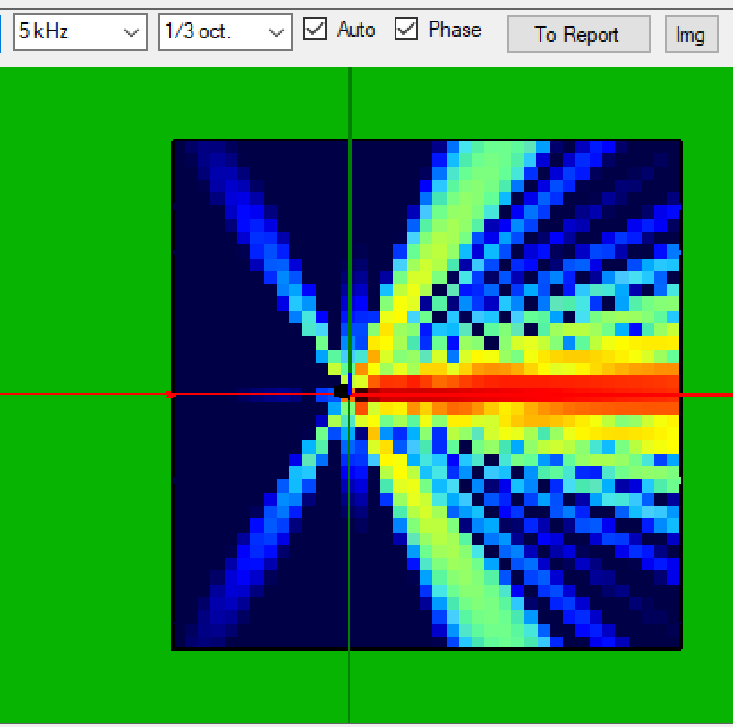
Next frequency step.
Last frequency step of the sweep — the family of polar responses seen as one picture.
You can put sound only where the individual transducers also put sound.— the constraint we work under
So we need to do this kind of research over different models. I am going to put together a tool to do this easily and see results. Also I think any coverage would be helpful for the Digital Horn, although for very pronounced or asymmetrical coverages I have seen something like these words — "you can put sound only where the individual transducers also put sound". So this array with SH25s would be a high-Q cluster with not-so-pronounced coverage lobes, but very good for soft aiming with precision.